Injection molding is a widely utilized method for producing high-quality, precision-engineered plastic components. However, achieving exact and consistent tolerances can present challenges, particularly when dealing with complex geometries and strict specifications.
Tolerances refer to the allowable variations in dimensions, and they play a crucial role in ensuring the final product’s functionality and effectiveness.
In this blog post, we will explore injection molding tolerances and outline four strategies for optimizing them. By following these guidelines, manufacturers can improve process control, reduce waste, and deliver high-quality products that meet customer expectations.
Establishing Tolerances in Injection Molding
Defining tolerances is a critical component of the design and production phases in injection molding. Tolerances refer to the allowable deviation from specified dimensions and are vital for ensuring that the final product meets performance requirements. When developing tolerance standards for injection molding, consider the following key factors:
Key Injection Molding Tolerances for Quality Assurance
Designers must address various types of tolerances when producing injection-molded components. The classifications of tolerances outlined in the injection molding tolerance guidelines include the following elements:
– Dimensional Tolerances
– Straightness/Flatness
– Hole Diameter
– Blind Hole Depth
– Coordinate/Ovality
Each tolerance chart or table provides multiple tolerance alternatives for various materials and size ranges, some being more economical while others offer greater precision at a higher cost. In addition to dimensional tolerances, designers must specify tolerances for critical features, such as holes intended for fasteners. Depending on the function of the part, a general tolerance and flatness callout may also be necessary, particularly for foundational components in medical devices.
Strategies to Optimize Injection Molding Tolerances
Achieving precise tolerances in injection molding can be challenging due to numerous factors, including material properties, mold design, and processing conditions. Tolerances are essential for ensuring that the final product meets both aesthetic and functional standards. Manufacturers can enhance consistency, reliability, and cost-effectiveness through the following techniques:
-
Design for Manufacturability (DFM)
When designing parts, it is essential to consider moldability. Our DFM evaluation process identifies critical design considerations aimed at optimizing product fabrication, allowing for immediate identification of design flaws. Utilize these design principles to ensure your final injection-molded product maintains exact dimensions.
– Overall Size and Structure
Injection-molded components typically have a tolerance of 0.1 mm for consumer applications, while tighter tolerances of 0.025 mm are necessary for medical devices. Designers should account for how each part fits into assemblies, known as tolerance stack-up, considering required clearances and potential interferences, such as those created by fastener heads.
Oversized injection-molded components tend to experience greater shrinkage, making it more difficult to maintain accurate proportions. Consequently, it is more challenging to achieve tight tolerances for individual features and overall part dimensions.
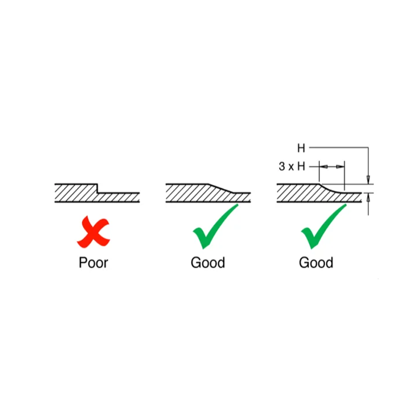
– Wall Thickness
Thick sections tend to sink during cooling, as they cool more slowly than thinner sections. This can result in defects such as divots due to the molten core shrinking inward and pulling the outer walls. To mitigate these issues, ensure uniform wall thickness throughout the component, as parts with inconsistent wall thickness often warp, affecting their ability to meet tolerances.
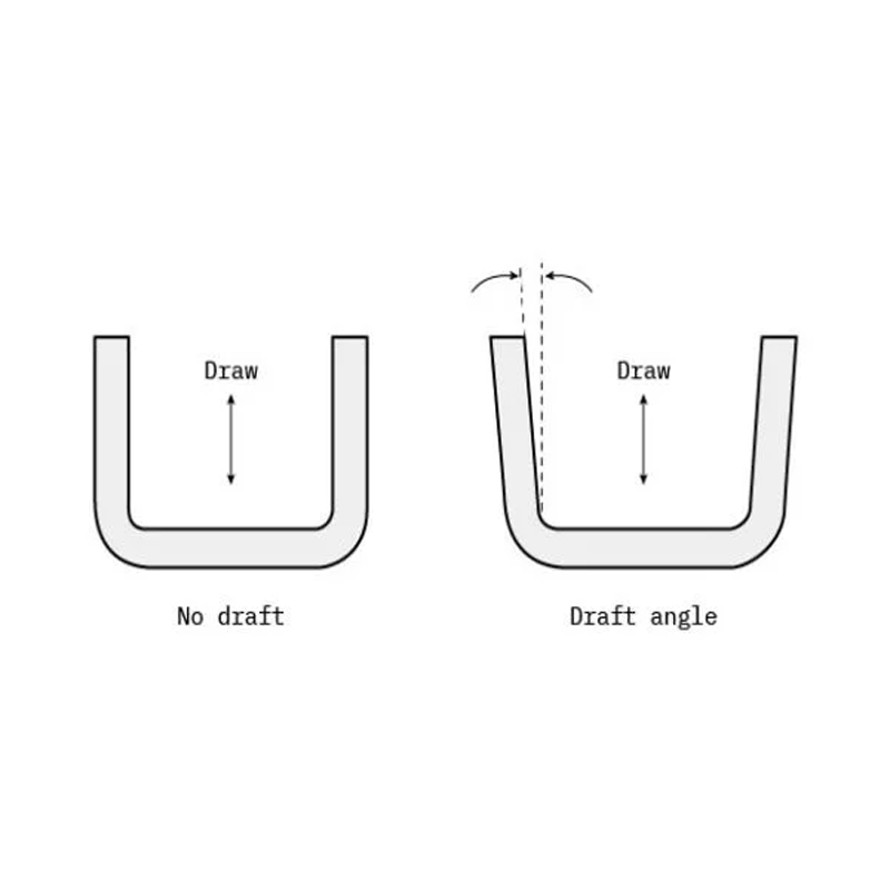
– Draft Angles
Compliance with design standards is crucial when accounting for manufacturing limitations in the injection molding process. For effective ejection from the mold, components must incorporate draft angles. Adjusting the draft angle can modify part dimensions, subsequently influencing expected tolerances. Generally, an increase of 1 to 2 degrees in draft angle is effective in most scenarios.
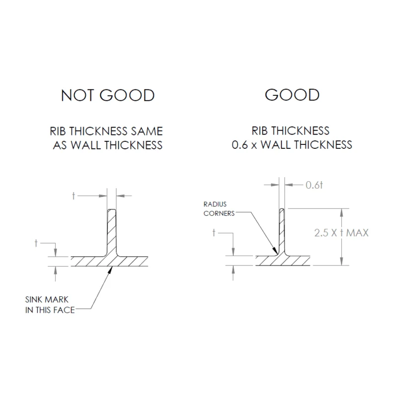
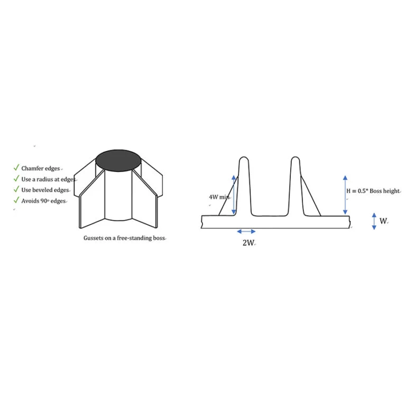
– Boss Features
– Rib Design: Effective rib design for boss features enhances stiffness while minimizing material usage. The rib thickness should comprise 60% to 80% of the structure’s width, which helps reduce sink marks and maintain a quality surface finish.
– Fillet Radius: Implementing a fillet radius for boss features is essential to prevent stress concentration at sharp corners. A fillet radius between 0.5 to 1 times the thickness of the structure is advisable.
-
Select the Appropriate Material
Choosing the right resin is paramount. Each material exhibits unique properties that affect its cooling behavior, flow characteristics, and final solidification. Selecting a material tailored to the application can be the difference between success and failure of the part.
All materials contract as they cool in the mold, making it critical to consider how the mold accommodates the component’s shrinkage rate during material selection. To achieve desired tolerances, tool design, material selection, and part design should be considered holistically.
-
Account for Tool Design Considerations
The design of the tooling significantly influences injection molding tolerance levels. Tools must be engineered precisely to ensure that the finished parts meet specified parameters. Utilizing high-quality materials in tooling is vital to mitigate wear and damage over time.
– Cooling System: An effective cooling system is necessary to maintain uniform temperature throughout the tooling. Proper cooling reduces thermal stresses that can impact the precision of injection molding processes. Optimized cooling channels should be integrated into the mold design to facilitate consistent temperature control, resulting in more accurate and repeatable molding.
– Mold Accuracy: The mold’s tolerance is critical to achieving the desired precision in injection-molded components. Tolerance refers to the allowable deviations from specified dimensions, which must remain within a defined range for proper functionality. Careful consideration of mold tolerance during the design phase ensures that the mold can produce components with the required accuracy. While tighter tolerances yield more precise parts, they can also increase the cost and complexity of tooling.
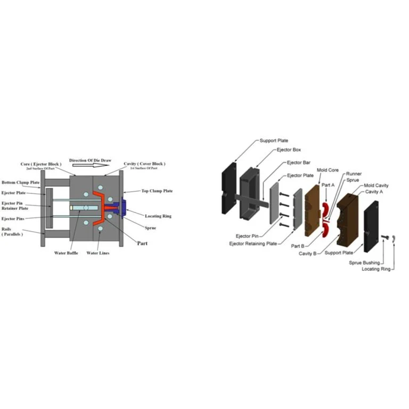
– Ejector Pin Location and Ejection Systems: The positioning of ejector pins and the ejection system affects the final product’s tolerances. After a part is formed, it is removed from the mold using ejector pins. The location of these pins must be meticulously planned to prevent damage during ejection. The ejection system should be calibrated to ensure consistent and reliable removal of parts from the mold, as improper ejection can lead to defects that compromise tolerance.
– Gate Location: The gate location impacts the finished product’s tolerance by controlling where molten plastic enters the mold cavity. It is essential to position the gate to facilitate optimal material flow and minimize potential defects that could affect part tolerance. An improperly located gate may result in sink marks, warping, or other flaws that diminish overall accuracy.
-
Implement Process Controls for Quality Assurance
Scientific molding integrates three key aspects of the molding process: hold, fill, and pack. This methodology enables manufacturers to produce reliable components consistently, whether it’s the first or the hundredth iteration. This environmentally conscious approach guarantees dimensional consistency from start to finish and ensures reproducibility throughout the production process.
The functionality of the final product hinges on specific attributes. Therefore, it is advisable to identify and emphasize up to five Critical-to-Quality (CTQ) elements in your CAD framework, including tolerances. By prioritizing these critical specifications, we can focus our efforts on meeting your requirements while ensuring consistency throughout manufacturing.
Injection Molding Tolerances Standards
The injection molding tolerances standards establish permissible ranges of dimensional variation for plastic components produced via injection molding. These standards are essential for ensuring that the final product meets specified requirements and performs as intended. Factors influencing injection molding tolerances include mold design, material properties, and operational conditions of the injection molding machine.
Organizations such as the Society of Plastics Engineers (SPE) and the International Organization for Standardization (ISO) set the benchmarks for injection molding tolerances. Adhering to these standards is vital for ensuring the consistency and quality of injection-molded plastic components.
Conclusion
Achieving precise and consistent tolerances can be difficult, especially when dealing with intricate geometries and stringent specifications. Tolerances play a crucial role in ensuring the final product’s functionality and usability. To produce high-quality products that meet customer needs, it is essential to design components for manufacturability, evaluate overall size and structure, ensure uniform wall thickness, incorporate draft angles, and select the appropriate materials.