Features:
| Attribute | Value |
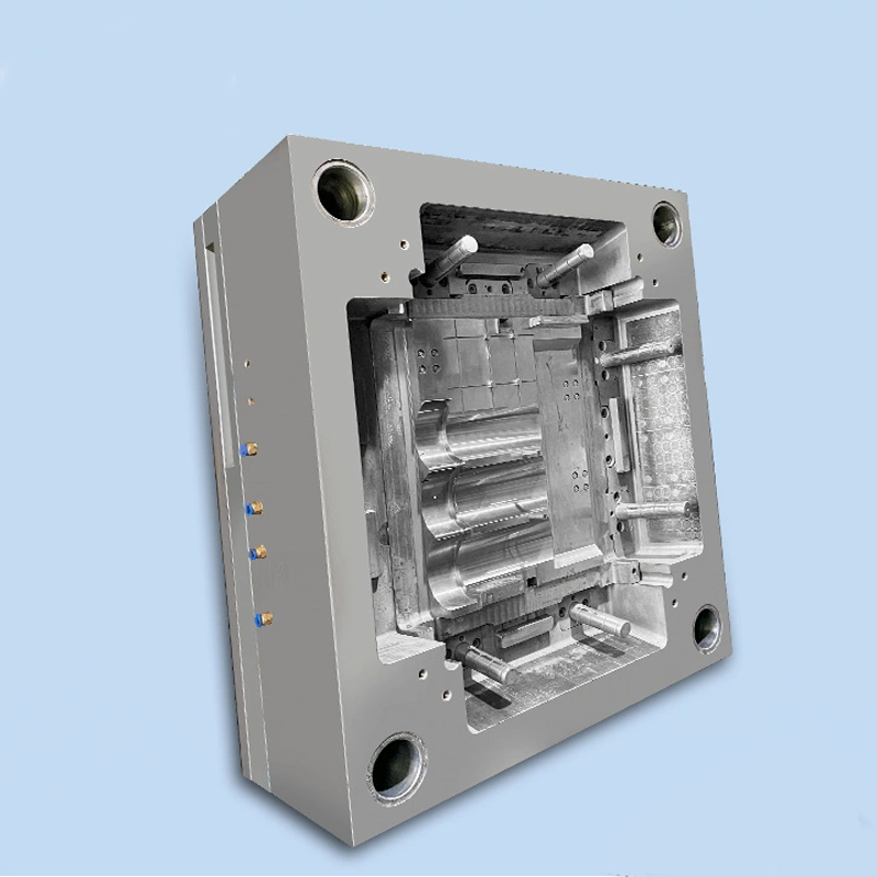
| Mould Type | Plastic Injection Mold |
| Mould Material | P20/718/738/NAK80/S136 |
| Mould Base | HASCO, DME, MISUMI, JIS, LKM etc |
| Mould Runner | Cold Runner/ Hot Runner |
| Mould Gate | Slide Gate/Sub Gate/Pin-point Gate |
| Cavity | Single / Multi Cavity |
| Designing Software | UG/PROE/CAD/SOLIDWORKS |
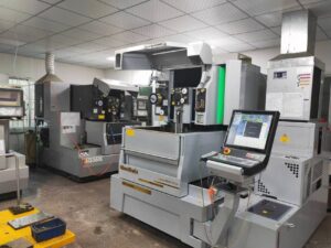
| Moulding equipment | CNC, Wire Cutting, Milling Machine, EDM |
| Raw-material | ABS, PP, PC, PA6, PA66, PVC, POM, PMMA, PS etc |
| Package way | Wooden pallet, carton |
| OEM | Welcome and please offer 2D/3D file or sample |
| Lead time | About 30 days |
Parting Surface Design Considerations
When designing a step parting surface, it is essential to include an insertion inclination angle ranging from 3 to 5 degrees, with a minimum requirement of 1.5 degrees. This angle facilitates smoother processing and handling, particularly when multiple step surfaces are present on a single parting line. Maintaining consistency in the angle application (angle A) across these surfaces streamlines the manufacturing process.
Additionally, each identical surface must have an adequate sealing distance to prevent plastic melt leakage during the injection molding process. Properly sized sealing gaps are crucial for effective material containment. For parting surfaces with significant height variations, such as curved or inclined areas, establishing a reference plane is necessary to support accurate processing and measurement.
Basic Principles of Parting Surface Design
Upon mold separation, the molded plastic should ideally remain on the half of the mold equipped with the ejection mechanism, typically the moving mold. Exceptions are rare, where the ejection mechanism is located on the fixed mold side.
For plastic products incorporating metal inserts, the cavity for these inserts is generally designed on the moving mold due to the inserts’ inability to conform to shrinkage. This design can complicate the demolding process. Achieving coaxiality becomes challenging when the design spans both the moving and fixed molds, often leading to potential manufacturing and assembly discrepancies.
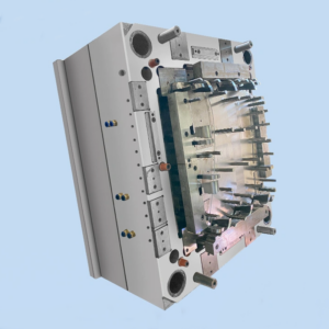
Mold locking requirements should be addressed by positioning the plastic products at the clamping site of the mold. This approach can significantly reduce the required locking force. For parting surfaces with curvature, a positioning mechanism is essential to preserve the product’s integrity and prevent any alteration to its final shape, particularly if the product features intricate details such as diamond or tangent lines.
Selecting a parting surface with a smooth profile and minimizing sharp corners is crucial to maintaining the quality and shape of the final product. Although achieving a perfectly smooth surface may not always be possible, efforts should be made to reduce potential defects. Additionally, the size and placement of internal mold inserts should be carefully planned to ensure optimal functionality.
Production Process Overview
- Design and Engineering:
– Concept Development: Partnering with clients to define precise requirements and design a mold that aligns with the specific dimensions and functional needs of the auto battery box cover.
– 3D Modeling: Using advanced computer-aided design (CAD) software to create detailed 3D models, enabling visualization of the final product and detection of potential design issues or areas for refinement.
– Mold Flow Simulation: Performing a mold flow analysis to model the injection process, ensuring efficient material flow and identifying possible defects such as warping, sink marks, or air entrapment.
- Material Selection:
– Material Selection: Choosing premium materials for both the mold and the battery box cover, with attention to properties such as durability, thermal resistance, and wear and tear resistance.
– Mold Steel Specification: Selecting a suitable steel grade for the mold to endure the injection pressures and temperatures, while maintaining dimensional accuracy and surface quality.
- Mold Manufacturing:
– Precision Machining: Employing CNC machining and other high-precision tools to manufacture the mold components, ensuring strict adherence to dimensional tolerances and consistency.
– Surface Treatment: Applying appropriate surface treatments, such as polishing or texturing, to enhance the mold’s performance and achieve the desired finish on the final product.
– Assembly: Assembling the mold components with meticulous attention to alignment and fit, ensuring smooth operation and reliable production.
- Testing and Validation:
– Trial Production Runs: Conducting initial production trials to assess the mold’s performance under real-world conditions, identifying and addressing any issues to optimize the injection process.
– Quality Assurance: Executing comprehensive quality inspections of the battery box covers, verifying defect-free production, dimensional accuracy, and adherence to design and material specifications.
- Production and Maintenance:
– Mass Production: Utilizing the validated mold for large-scale production of auto battery box covers, ensuring consistent quality and output throughout the manufacturing process.
– Routine Maintenance: Implementing a regular maintenance protocol for the mold, including cleaning, lubrication, and minor repairs, to prolong its service life and sustain peak performance.
